
| | Home | Contact us | |
| Media Splitter MS12 Mk2 |
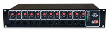
12 Channel Media Splitter
An audio distribution amplifier primarily designed to feed multiple
ENG cameras from a single microphone at media events. Typical use is to
feed the Media Splitter with a line level signal from an AUX output on
the local PA system.
Available in 12 channels only.
Key Features...
- Each output has its own IC buffer amplifier to provide a high degree of isolation between outputs.
- The input and all outputs are transformer balanced using a total of 13 audio transformers.
- Individual level controls on each output are adjustable continuously from mic through to line level.
- Individual earth lift switches on each output.
- Genuine Neutrik XLRs throughout.
- A LED ladder level meter with selectable peak hold provides a visual indication of signal.
- 1kHz +4dB alignment oscillator (rear panel).
- Headphone socket and internal monitor speaker (rear panel).
- Only the output level controls and earth lift switches are on the front panel. All other controls are on the rear panel away from unauthorized fingers.
| The Rear Panel |
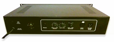
The following is mounted on the rear panel...
Input gain control. Adjustable over the range of -15 to +15dB
The input is nominal line level as it is envisaged that a mixer would
be available to drive the local PA system and the Media Splitter.
1kHz alignment oscillator. It delivers a fixed +4dB to the output channels. This enables cameras to be setup before the main audio feed is available.
Monitor amplifier. It drives headphones or an internal 2 (50mm)
loud speaker. The speaker is intended only as a means of verifying
the presence of audio and as a fault finding aid in setting up the system.
Connecting headphones to the headphone socket will mute the speaker. The
monitor amp has its own level control.
| Connections and Setup |
Operating Levels.
Output +4dB when fed with +4dB input level. (unity gain)
Test conditions:
Rear panel gain = 0dB, Front panel level = fully CW
The Input.
This is a 3 pin XLR male with a parallel female for convenient looping.
Because the input is transformer balanced , all 3 pins on the
input XLR must be wired. This happens by default if the source is
balanced.
If the source is unbalanced, wire pin 2 hot and pins 1 and 3 earth.
(Pins 2 and 3 may be swapped if desired)
Failure to wire all 3 pins will run the input transformer single legged
and will usually result in very little audio.
The Outputs.
12 output XLRs are mounted on the front panel.
While the output XLR connectors are wired balanced, unbalanced devices
may also be connected.
There are several ways to wire an unbalanced cable to a balanced output.
The electronic architecture used in the Media Splitter allows every
possible wiring arrangement to work.
The preferred wiring for unbalanced loads is...
Pin 2 hot and pin 1 earth. Pin 3 may be left open or tied to earth.
(Pins 2 and 3 may be swapped if desired).
Basically, pick any two pins and youll have audio. The third
pin can be left open or tied to ground.
Phantom Power from a camera can also be fed into the outputs with no
problems. It will not cross feed into other outputs.
Setup
Set the output level control of a selected channel on the Media Splitter
fully counter clock wise
Connect a camera or similar device to that output.
With audio or tone present, increase the channels output level control
until the cameras sound level meter is happy.
There is no need to change the cameras normal record levels or its
mic/line switch setting. This is a good thing as some camera operators
dont even know they have a mic/line switch!
LED Ladder
The LED ladder has a selectable peak hold function.
To toggle the Peak Hold function;
i.e. If it is on, turn it off. If it is off, turn it on.
Set the rear panel Oscillator switch to ON. Apply mains power.
Within 1 second, turn the Oscillator switch OFF and then ON again.
The status of the Peak Hold function will be displayed for 1.5 seconds.
If Peak Hold is active, only the Clip LED will light for 1.5 seconds.
If Peak Hold is not active, only the 2 Yellow LEDs (+10 and +5 LEDs)
will light for 1.5 seconds.
| Specifications |
0dBu = 0.775 volts
Input Level
Line level. +24dBu Maximum.
Rear panel gain control is adjustable from -15dB to +15dB
Input Impedance
20K ohms balanced or unbalanced.
Transformer isolated. Floating input.
Outputs
Transformer balanced with individual earth lift switches.
Output Level
Continuously variable from mic (-45dBu) to line level (+4dBu).
Output Impedance
Less than 300 ohms.
Headphone Output
Suitable for 8 to 600 ohm headphones.
120 ohm source impedance as per IEC 61938.
Typically 2 volts out with +10dBu input.
Connectors
Output: (Front panel) Twelve 3 pin Neutrik XLR male.
Input: (Rear panel) Two 3 pin Neutrik XLRs.
Male in
parallel with a female for convenient looping.
Frequency Response
35Hz to 24kHz +/- 1dB
Test conditions:
Input +10dBu, Rear panel gain = 0dB, Front panel level = fully CW
Total Harmonic Distortion + Noise
Typically less than 0.03% above 100Hz, rising to 0.1% at 30Hz.
Test conditions:
Input +10dBu, Rear panel gain = 0dB, Front panel level = fully CW
Power
110/230/240V 50/60Hz mains power. Specify at time of ordering.
30 watts maximum.
Dimensions
2 unit high 19 rack mount all metal chassis.
Depth: 270mm with no XLR connectors plugged in.
Weight
5.3 kg (11.7 pounds)
| Brochure |
| Download the brochure
for the Mk2 Media Splitter.
in Adobe Acrobat format . |
| Home | To top | Contact us |
Copyright © 2024. The Leon Audio Company. All
rights reserved.